instagram

Saturday, February 22, 2014

Shapeoko assembly and testing

I received my Shapeoko last week which was extremely exciting. I ordered the full kit which (as the name implies) comes with everything you need to get started. Well, except for a jumper that is not documented (see below).

There are lots of little upgrades that you might want to look at still - the new baseboard and bumper switches being high on my list to get. It uses an Arduino for control (which despite 15+ years playing with embedded stuff I'd managed to avoid till now). I was really really really tempted to not get the electrical kit and make my own controller (after all it could basically use the software and hardware from Sparky BGC and/or my ESC) however I really want this to be a tool rather than a project in itself so sucked i up.

 Of course I had to immediately start assembling, so that shot two nights of studying, but oh well. I snapped a few photos along the way.


Assembly


Stuffing all the bearings into these took forever and killed my fingers

This gives a little spring to the z-axis in case of a crash

The rollers for all the axes. I didn't notice at this point you should add the screw terminals if you want them. I figured I would solder but they were ultimately easier so I had to get them on later. Oh well.


Finished X and Z axis
End of night 1. Almost there - just the last mounts (which involved lots of tapping holes) and then on to electronics.
And all finished!

I did print a "Hello world" but it looks fairly ugly because of sloppy pen mounting so I will not show it :).

One thing to look out for though, is there is an error in the documentation unless I missed something. For grblShield it says to use $2=320 but the issue with this is that it assumes 2x microstepping on the z-axis. The way the grblShield comes configured, it is set for 8x microstepping. If you follow the instructions as written, your z-axis will only move 1/4 the amount it is meant to. You need to add a jumper for the z-axis to make it work properly (or probably $2=1280, but I did not run like this because it reduces the z-axis torque).  You can find more information here.

Toolchain / Workflow

Jumping in to CNC manufacturing is fairly overwhelming. I know a few things from work where we use Catia and a nice Hermle 5 axis (and by we I mean other people and I'm just peripherally involved). I spent some time reading around on various programs for both the CAD (design) and CAM (toolpaths) stage of things. My ideals were open source and runs nicely on a mac. I'm found something that satisfies it although it is possible I'll eventually fork over some money if these end up too limiting.

But I settled on two workflows, the former being the only thing I have used so far:
  • Most things: FreeCAD for design and generating toolpasses with PyCAM
  • Artwork: Blender with the BlenderCAM add on (I've used Blender previously)
I really like FreeCAD so far because of the parametric modeling. I like the ability to simply type in the dimensions and angles and have it take care of the details. I recommend taking a look at this tutorial. It also has a lot of similarities with what I learned from Catia. I'm using the 0.14 version right now, which I think isn't the official release. So far it's worked fairly well, although definitely has some bugs. So the first thing I did was a simple heart to try and convince my girlfriend this hobby is something she will like :).


I did this by using the draft mode to create the face (using two arcs and two straight lines) and then extruding that to make a solid. I realized afterwards this is NOT the right way to use FreeCAD so will talk about it later. From there I saved the shape as a .stl file and loaded it up in PyCAM.

For PyCAM I would definitely recommend getting it from the source. The precompiled version I could only get a really silly toolpath that ended up taking a solid hour to cut. Tons of lifting the spindle up and then down, cut a little, and repeat. Unfortunately I forgot to save a screenshot of that ridiculousness. Anyway with the latest version I used the "waterline" cutting pattern to generate essentially what I wanted. 

Although it would be nice to have the path in something not red since for me red on black is super low contrast. Luckily since it is OSS I can change that :D. Finally upload that path through the universal gcode sender and cut away :). These videos were taken with the earlier version of PyCAM so you'll see more silliness in the path.


All of the cutting was done with the"Solid Carbide 2 Flute" bit from Inventables using some scrap wood I had sitting around.


Happy Valentines day!

One question I did have after playing with this: what is the best place to designate as "0" for the tool. Right now I'm putting it towards the top of the material and then zeroing the coordinate system. However that ends up making my waste board a little sad when the material isn't the precise depth. I'm thinking about zeroing out on the table surface so that it can simply start a little high, but then it gets awkward because you need to move the material in and out for zeroing.

Sad waste board

More serious design

Now I knew the basics were working, I wanted to design something a bit more sophisticated. I'm trying to build a hinge that can be actuated in a fairly simple way and this will be a prototype of it. At this point I realized the right way to do this is using Part Design mode and creating constrained sketches. I'll defer to the hackaday tutorial for details on how to do these things.
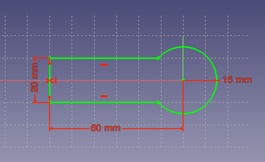
Create the outline of the piece

Make it a pad that comes up

Make a sketch on the top face of how I want to shape a pocket

Add the filets at the corner to make it machinable

Get it fully constrained so it is valid. At this point it turns green.

Make a pocket in the piece that is that shape

And another pocket at the end to lower the profile of the hinge area

And finally a hole for where the opposite piece will mount

More serious CAM

From this model I exported the stl file and loaded it into PyCAM. 

Here you see the model all loaded up. Note this time "0" is below the piece which I need to remember

Tell PyCAM the bit I am using
So the strategy for cutting things out I like is "waterline" which goes around the edges. However, because I need to cut a big chunk of stock out I need to do this first because the drop down area won't be caught by the waterline strategy. I'll do this but restrict it to the part of the piece that is relevant.

So a process named bulk removal that will be allowed to have some slop (0.5mm error)

Bounding box that only covers the area I need to remove material

Set up a task using these tools, strategies and area

Which gives a pretty reasonable path
Now that the stock is milled down there, waterline will work for the remaining area.

Use the waterline mode to cut around the edge

Bounds that cover the whole model now

Set up a task to generate the pass using the correct process and bounds as well as the right collision model

And finally the tool pass to generate this part

Cutting

I made a mistake the first time I generated this tool pass. I set the safety margin to 5mm which I had previously done when the "0" was on the top of the piece. In this case, that made the tool transverse between locations THROUGH the material. It took me a while to realize what was happening and it produced quite a mess. You can see this near the end of the video.

CNC Joint from James Cotton on Vimeo.


My second pass was almost perfect. However, right at the end when it finished the middle hole the whole thing was disconnected and started spinning around. That ripped it nicely and luckily only bent the bit and didn't break anything. You have to be sitting by the power switch on this thing!


To work around this I went ahead and added a support structure:


Which leaves it attached. However, I forgot to enable it for the collision detection so my second one almost went the same way. Luckily I stopped it in time and pulled the piece out. In the future I will definitely make sure to use supports properly and manually cut them when the piece is done.

Also for the final version I need to make sure the pocket inner cutting goes to the same depth as the waterline pass. That ended up not lining up perfectly and i'm not sure why yet.

Other component and finished!

I also machined the other side of the joint. This time I figured out how to use the grid cloning feature in PyCAM which was nice to make it one operation (which luckily didn't fail). This time I also got the supports to work properly.


Thanks Inventables

Both for making this available at a reasonable cost and having pretty good documentation. Also it just seems like a company run by people that are nice which is awesome. When there was a mixup on some shipping stuff they paid the difference even when I offered to, which is just really nice.


Sunday, January 26, 2014

Path smoothing demonstration

I commented in my previous post that there was some oscillations in the flight when it would be asked to do impossible things (e.g. sharp turns with constant velocity). Kenn wrote a really nice (and necessary) feature for the fixed wing code that would fillet the turns and generate nice smooth curves when you request impossible flight plans. I ported this to the general waypoint editor so you can apply algorithms to a flight plan, such as smoothing it.

The nice thing about this, is you can take a flight plan with sharp edges and generate a nicely smoothed plan:


I also updated the VTOL follower to properly handle landing waypoints and finally had a chance to test it out. The result was quite nice
This shows three flights plotted on top of each other. There are one or two spots where it diverged a bit (it was a bit breezy today) but generally it behaved quite well. It also removed any obvious ringing like the flights last week. Unfortunately, I haven't written the matlab code to visualize curved flight plans, so I can overlay the intended plan. However you can see it in the previous figure and it's pretty much spot on.

The landing waypoint type also worked well, which is nice. However, it is an important warning that with multirotors you can have the landing location a good distance from the previous waypoint. In this case it just starts decending and going sideways rapidly. I might update it to have a similar sequencing to the RTH sequence: fly to landing location at a fixed altitude and then descend.

So here is the video. The first half just shows making the path and is kind of boring. Sorry about the excessive reflexion from my screen. The second half shows the flight and also overlays the telemetry data for comparison.

Saturday, January 18, 2014

Navigation testing and post-crash disection

Another fairly typical day or two of testing navigation but with some amusing crashes.The first day was uneventful, but the second less so:


The navigation portion worked really well. I flew a 7 point sequence twice and got very nicely reproducible results.


This shows the log from two sequential flights. You can see the blue trace (real position) follows the path desired (green) quite closely. It's also quite interesting to see that the errors in how it flies the path are quite reproducible. Specifically trying to ask for a sharp angle makes it start oscillating. Parly from the amount of oscillations you can see that this is underdamped and I'll be trying to tune it.

However, the other half of the problem is that the path isn't achievable. Quads cannot make instantaneous turns. We have some code that can reshape paths to something more achievable.

Before filleting path

After filleting

Unfortunately I didn't get a chance to test that yet. When I was testing I did get good performance on the navigation. However, I had two crashes that were pretty bad. In the middle of flying the path it just randomly fell out of the sky.

Luckily the second one I got a log which showed the culprit. Once I started doing nav from takeoff (i.e. arm and flip switch) I kept leaving the throttle in a low position. This resulted in a disarm timeout after 30 second. I decided to use the awesome Python log parsing that Stac has written to visualize the results, as well as the new feature in matplotlib for XKCD-style plots.

Analysis from logged data from crash

So this plot pretty clearly shows the drop in altitude from the baro. While that is happening the desired throttle goes to max, but the actual PWM output drops because the system is disarmed. Unfortunately telemetry didn't catch the change in FlightStatus to definitely prove this, but the time from arming to falling is 30 seconds (both times in the video) which is pretty much conclusive as far as I'm concerned.


Poor quad will be waiting on some new parts though :(. Impressive that it took two of those hits


So the simple solution to this is to keep throttle above zero while performing anything autonomous. This is even on the wiki and something I knew about. I'm hesitant to remove the disarming right now though since when I had the flyaway attempt at OP that was the only thing that ultimately brought it down. For sure the GCS should be honking a huge alarm at you (and Android should) if you are doing this though since it is a guaranteed crash combination.  I opened an issue to discuss this https://github.com/TauLabs/TauLabs/issues/1078 .

Monday, January 13, 2014

EEG Stuffing and Testing

So my Sparky EEG board data boards arrived the other week. I'm quite happy with how they turned out. I used a 0.8mm manufacturing to have something smaller to mount on the head and it seems sufficiently strong.

Before
And after
Before getting into the build, I'll cut straight to the cool punchline.


I finally had the opportunity to solder up one up yesterday. The first board I pasted was a little heavy. I'm not used to the 0.8mm boards I ended up using. However, since I only expect to solder one of the 10 boards I got it seemed not worth worrying about so I immediately set the rest of them up as a platform and got a great solder application. The rest of assembly was great and there were a few solder bridges that were easily touched up.


Then the super fun (read: tedious) part of populating the board.


Finally throw it in the toaster oven until done. Only a few shorts which were easily fixed.


 It was pretty easy to bring the board up and get it reading the accelerometer and gyro since that isn't changed from Sparky proper.

 However, I wasn't initially getting any ID when I attempted to query the ADS1299 chip, so it was time to bring out the good old OpenLogic analyzer. Finally I realized I didn't have the SPI Mode correct for this chip and the data phase was wrong. Once that was fixed the communications were flawless. A few hours of writing a driver to work with the chip, bring it up, get the inputs in the right mode, etc.


At this point it was essentially working, and I plugged it into the android app to be able to check out the data (although I can also use the Tau Labs GCS). I went ahead and soldered a straight header on for now so I can test it on the bread board, adding another 10k between VIN1P and SRB1 and then using the 7.8 Hz lead off detection. The data looks pretty good.

With the period matching pretty well. I'm not sure right now why it doesn't look more sinusoidal.


Sunday, January 5, 2014

Loiter mode and more RTH testing

So I met up with the Houston flying crew yesterday and had the chance to do more testing of the new RTH and loiter modes.

Loiter testing

One of the changes in this code is that now the VTOL control loop actually tries to control acceleration (and through that the airframe angle). This is inspired by the Arducopter code and seems like a sensible idea since it makes the control laws more linear. It does mean that units of the parameters change so it was necessary to retune.

It took me a bit to find good tuning parameters but overall I was happy with the results by the end of the day. Here are my final gains:

  • HorizontalPosPI.Kp was 0.8 with zero Ki
  • HorizontalVelPID.Kp was 2 with a Ki and Kd of 0.


Tau Labs Loiter and RTH testing from James Cotton on Vimeo.

The loiter mode is very similar to the Arducopter code. You apply pitch and that will move the set point for position hold forward at a rate proportional to the stick input. Roll moves it sideways.

Mike suggested an alternative control scheme: when the stick input is outside a certain range you fall back to stabilized mode so you can basically free fly, then when you release it goes back to PH mode where you are. I might implement that later and let people compare the two.


I was doing this on Freedom so I had Overo logs afterward to look at. You can see this above - the black dots indicate updates of the setpoint and when I use the stick movement the position moves. The quad does a really nice job of tracking it. If we really zoom in on a steady segment we can see the amount of drift:


You can see there is above 1 meter oscillation around the setpoint. This probably reflects some gains that are too high. I also didn't have any integral yet and it was fairly breezy which explains the residual error. I definitely need to do some work on how to compute optimal tuning parameters for PH and navigation.

Return to home

As you can see in the video above, RTH is also working pretty reliably. I think I probably did about 5 or 6 runs with it and it usually landed within a meter of home. It doesn't turn off the motors when it lands right now - that will come later. The stability during the landing decent wasn't quite as good as some of the other platforms people were showing off - I'm not sure yet if that is a tuning issue or what.

Here are three RTH flights overlaid. You can see it pretty reliably flew back at the right altitude and landed in the correct location. There is also a view from the top. Ignore that trail for one of the flights once it lands - that is just dragging on the ground.


Some interesting points. The middle flight is the one in the video. You can see where it starts shifting back and forth is when the wind was gusting. I should have remembered to do a test flight above the 15m minimum RTH altitude. The RTH paths aren't quite as straight as I would like, but that also comes up to tuning.

Overall it is working well enough to get the copter home, so that is good.


Monday, December 16, 2013

EEG architecture and software development

Plan

So now the EEG board is out for manufacturing it is time to start designing the software. I figure I can use an existing Sparky to generate fake data and begin on the android application. Here are a few of the features I want to have in the app:

  • Configuration (e.g. setting reference electrodes and bias configuration)
  • Noise measurement
  • Waveform visualization (with filtering)
  • Spectra visualization (as well as pseudocolored time plots)
  • Basic control app (e.g. 2-D cursor that you try and move around)
So this will be done by modifying the existing software stack (android app and sparky firmware). I think I will keep the UAVO manager in place and use that for general settings and status information. This can work via the USB HID interface.

Initially for the data stream I will attempt to run it via UAVO updates as well to try for the greatest reusability of the code. However, if this doesn't work then I'll use a VCP stream. This just gets a bit awkward when using TCP as then we will need two independent streams (e.g. separate sockets).

Since the data is 24 bits wide, I could either pack it into int32 fields or just use real units and represent it as a single - the latter seems preferable to me. I'll make an object which has a sample counter and an array of singles. In the future if I use multiple ADS1299 then I can just go ahead and use a multiple instance UAVO.

So with this plan the steps going forward are:
  1. Create the data UAVO
  2. Create a firmware module that in the future will read from the ADS1299. For now it will just generate synthetic data at 200 Hz.
  3. Check that all the samples are received
  4. Create an android activity that plots the traces

Implementation

Streaming bandwidth

With a modified firmware in hand sourcing sin waves sampled at 200 Hz, I got hacking on the Android app. I wrote a telemetry task that runs within the service context and keeps a running buffer of the last few seconds of data. It monitors for any skips in the sample counter and at that rate I see about 1 or 2 skips every second. Not perfect but good enough for now. It's comfortably sustaining 10 KB/s.

Later I'll try and determine if those are skips on the firmware transmission side or somehow they are dropped updates on the android side. The event system doesn't indicate any missed updates so I'm guessing that is what is happening. It's pretty nice because the built in logging for the UAVs is working for this transparently, so I can email the logs and process them with the matlab code for visualization.


The top row shows the diff on the sample index. It looks like most of the time there is a missed update there is a zero for the counter difference - so I'm guessing there is a timing error  on the flight side and it is skipping one sample and then sending duplicates of the same data point. Since the whole point of this is streaming this data I will modify telemetry to have a special queue that actually stores the history of values to send instead of pointers to which object to send. It might be easier to have the EEG module try and pack the data too if that doesn't break telemetry talking to the the USB comm device.

Visualization

For now I just wanted a simple streaming graph. I'm using the GraphView library which is pretty straightforward and seems to perform well.


And then you can plot all the channels. This gets a little tight on screen real estate and also the update rate starts to drop a bit. For fancier visualizations like this I will probably need to come up with a more performant library. Also, without modifying GraphView it isn't possible to get the graphs all close to each other. Perhaps one widget that is directly rendering it all. However, this isn't a huge issue right now so I'll put it off.


Spectrum

It can also plot the spectrum of the traces. No labels yet. The speed seems reasonable. 


Finally a simple spectrogram plot. None of the bells and whistles such as selectable channels or multiple channels yet, let alone windowing parameters. I'll leave that for when I know what I'm looking for.


This doesn't have a logarithmic scale yet, so the 2 Hz wave is close to the edge of the axis (full bandwidth 100 Hz).

Conclusion

Anyway, not a bad start I think. When it is charged tomorrow I'll try the app out on my Nexus 7. The bigger screen should be nice, although I think both it and the Nexus 5 are 1080p so no real pixels extra. Some of these functions I'll probably backport to TauLabs as having some of the plotting functions might be useful in the field.

Now It's really just wait for the board to arrive, or start reading about various signal processing algorithms and start hacking. However, those are typically better done on real data. The logging function will be extremely useful for having the code already written to record the sessions.


Saturday, December 14, 2013

EEG Design - time for something totally different

So I've wanted to build an EEG since I was in college and have numerous times spec'd out parts etc but never really got going. I've followed the OpenEEG project for ages, but technology wise it has remained rather stagnant. However, I just recently came across the OpenBCI project which pointed me at the ADS1299 chip and that has reinvigorated my interest in building a simple EEG. It's a long shot, but my ultimate plan is to create a system like this:


One thing I wanted to change from the OpenBCI design was to use an STM32 processor, since that is what I'm more familiar with. My goal is to avoid a lot of the safety issues regarding powering from a computer by running the data via my phone. This also gives me free perks like wifi, screen, bluetooth, etc. I should be able to pretty easily use the Android GCS as a basis, especially since that already has a lot of the core code for handling data via USB (HID and Serial) as well as WiFi (great for running simulations).

It was pretty straightforward to base the design off Sparky which seemed like a pretty good starting point - both in terms of electrical and mechanical properties. I had to extend the board a bit to fit the ADS1299 on there without going to four layers (I'm cheap and would rather a bigger board for the prototype). This is the end result:


The final board is 50 x 35 mm. I can easily shave 5 mm off the right side, but figured I'd leave it this size in case the next revision has more channels and needs that space.  Currently it is single sided so lots of room for expansion. And it's nice because I can reuse a lot of the code from Sparky and just write a new PiOS driver that speaks to the ADS1299 chip. For laughs, I left the accel/gyro/mag chip in case I want to have some kind of head tracking. Either that or try and use it strapped to my arm like a Thalmic labs wrist band.

Here is the schematic. Sorry the layout is really ugly - I should redo the TPS60241 component so the power comes in on the left and goes out on the right.


Layout

The ground plane is split to keep the analog electronics and digital electronics as separate as possible. The top plane on the analog side is AVDD and the bottom is AVSS. This is where a four layer design would be a bit better but for now I'll save some money.

Top:
Bottom:


Features

  • 8 Channels of single ended input, 1 driven bias electrode and one common reference electrode
  • Small (36mm x 50mm)
  • Utilizes ADS1299 chip
  • Optional reference and bias electrodes
  • Powered by USB. Small step up inverter generates a clean 5V after the input diode (probably not necessary if I never plan to use battery input). This can supply up to 25mA of current and the analog supply only requires 10.
  • Single sided power supply design (so patient will be at 2.5V relative to the board)
  • Solder pad allows using any electrode (routed out via SRB2) to serve as the negative input for the others. Alternatively use an additional reference electrode such as an ear clip.

Notes and quirks of the ADS1299

There were a number of things that were not obvious to me from a first pass through the datasheet. This is mostly a reference for me when I forget them after I came to a conclusion.

biasin - At first I assumed this input was something to do with computing the actual bias value. However, it is actually for situations where you want to reduce the number of electrodes going to the patient. In this case, you actually connect the biasin signal to the positive pin of a channel (i.e. electrode) which creates the path for the driven bias current. This will (obviously) introduce a small bias into the signal recorded on that channel, but this should be small and slow compared to the signals of interest.

srb1/2 -  Again, like with biasin, at first I assumed that both of these were meant to be treated as inputs. Either to provide a reference for the positive or negative inputs. However, (and again like biasin) this is to allow reducing the electrodes to the patient. In this configuration, you select an electrode (positive input) that will serve as the reference for others and route it out of SRB2. Then there is an external bridge from SRB2 to SRB1 which passes this signal back in and allows it to be the negative channel for all the other electrodes.

Input configuration

The ADS1299 has a pretty powerful analog multiplexer - but what is a tad counterintuitive or non-obvious is that channels can be mapped to inputs or outputs implicitly. The input mixer also gives lots of options. I'm going with what I think is the standard configuration and what seems most referenced in the EVM notes. This means the CHxSET register will be 000 for the mux "main" with SRB1 high. The positive values will all be routed out to the electrodes and the negative values will all go to SRB1.

Anticipated bias and reference

The full cable set will generally be used, at least at first. This means a reference electrode (e.g. earlobe) will come in to SRB1 and be connected to the negative input of all the channels. All of those channels will be averaged internally to compute the biasinv signal. The internal bias generation (2.5V) will be used for the positive input. The output (biasout) will then go to an electrode (via a protection resistor).

Thoughts

Inputs - OpenBCI used the negative inputs at SRB2 for their channels. I can't really understand why they did this (although it looks like it should work) but it won't be in "normal electrode" mode. 

I'm pretty tempted to switch a bipolar power supply like that in the EVM. The advantage of this is the patient is driven to zero volts relative to the digital electronics. This shouldn't ever be an issue provided everything is running from batteries but still is a potential safety improvement. It adds another chip though.

Isolation - one thing OpenBCI did quite nicely was solid isolation. This is important, especially if you want to make something commercial. I'm just goofing around and will try and only use it via phone or worst case when laptop is not powered by mains. To be honest, I just don't feel like putting all the components down for it.

Ground - Related to the the isolation issue, I hope I routed the ground appropriately. The ground plane is split - digital ground over the digital electronics and analog under the ADS1299. The digital grounds from the ADS go over to the digital ground plane and then are star grounded to the analog plane near the analog regulator. The AVSS and AVSS1 are both just connected locally to the ground plane rather than separately routed back to the star ground. The AVDD plane is similar.

Also one limitation of using my phone to collect the signals (provided processing power isn't the limit) is that I cannot simultaneously connect to a USB radio and control a quadcopter. However - if I get to the point that is the limit I'll happy redesign and use something like Freedom with more build in processing in the embedded board, or combine an RFM22b onto it.

Anyone have any comments on the schematic? I don't think I've got any glaring errors but you never know...

References

  • http://www.ti.com/lit/ug/slau443/slau443.pdf
  • http://www.ti.com/lit/an/sbaa188/sbaa188.pdf - good DRL notes
  • http://www.ti.com/lit/gpn/ads1299
  • http://www.openbci.com/technology-update/